- 您现在的位置:买卖IC网 > Sheet目录1251 > UM245R (FTDI, Future Technology Devices International Ltd)MOD USB PARALLEL FIFO DEV FT245R
�� �
�
�Document� Reference� No.:� FT_000202�
�UM245R� USB� -� Parallel� FIFO� Development� Module� Datasheet� Version� 1.04�
�Clearance� No.:� FTDI#� 124�
�7.2� Self� Powered� Configuration�
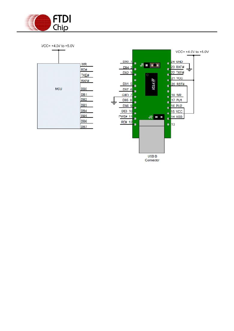
�Figure� 7.2� Self-Powered� Configuration�
�Figure� 7.2� illustrates� the� UM245R� in� a� typical� USB� self� powered� configuration.� In� this� case� the� link� on�
�jumper� J2� is� removed,� and� an� external� supply� is� connected� to� the� module� VCC� pins.� Figure� 7.2� illustrate�
�a� design� which� has� a� 4.0V� -� 5V� supply.�
�A� USB� Self� Powered� device� gets� its� power� from� its� own� power� supply� and� does� not� draw� current� from� the�
�USB� bus.� The� basic� rules� for� USB� Self� power� devices� are� as� follows:�
�i)�
�A� Self� Powered� device� must� not� force� current� down� the� USB� bus� when� the� USB� Host� or� Hub�
�Controller� is� powered� down.�
�ii)� A� Self� Powered� Device� can� use� as� much� current� as� it� likes� during� normal� operation� and� USB�
�suspend� as� it� has� its� own� power� supply.�
�iii)� A� Self� Powered� Device� can� be� used� with� any� USB� Host� and� both� Bus� and� Self� Powered� USB� Hubs�
�The� power� descriptor� in� the� internal� EEPROM� should� be� programmed� to� a� value� of� zero� (self� powered).�
�In� order� to� meet� requirement� (i)� the� USB� Bus� Power� is� used� to� control� the� RESET#� Pin� of� the� FT245R�
�device.� When� the� USB� Host� or� Hub� is� powered� up� the� internal� 1.5k� resistor� on� USBDP� is� pulled� up� to�
�3.3V,� thus� identifying� the� device� as� a� full� speed� device� to� USB.� When� the� USB� Host� or� Hub� power� is� off,�
�RESET#� will� go� low� and� the� device� will� be� held� in� reset.� As� RESET#� is� low,� the� internal� 1.5k� resistor� will�
�not� be� pulled� up� to� 3.3V,� so� no� current� will� be� forced� down� USBDP� via� the� 1.5k� pull� -up� resistor� when�
�the� host� or� hub� is� powered� down.� To� do� this� pin� 14� (USB)� is� connected� to� PU2� and� PU1� is� connected� to�
�RST#.� Failure� to� do� this� may� cause� some� USB� host� or� hub� controllers� to� power� up� erratically.�
�NOTE:� When� the� FT245R� is� in� reset,� the� FIFO� interface� and� control� pins� all� go� tri-state.� These� pins� have�
�internal� 200k� pull� -up� resistors� to� VCCIO,� so� they� will� gently� pull� high� unless� driven� by� some� external�
�logic.�
�Figure� 7.2� also� illustrates� interfacing� the� UM245R� and� a� Microcontroller� (MCU)� FIFO� interface.� This�
�example� uses� two� MCU� I/O� ports:� one� port� (8� bits)� to� transfer� data,� and� the� other� port� (4� or� 5� bits)� to�
�monitor� the� TXE#� and� RXF#� status� bits� and� generate� the� RD#� and� WR� strobes� to� the� FT245R,� as�
�required.� Using� PWE#� for� this� function� is� optional.�
�If� the� Remote� Wakeup� option� is� enabled� in� the� internal� EEPROM,� during� USB� suspend� mode� RXF#�
�becomes� an� input� which� can� be� used� to� wake� up� the� USB� host� controller� by� strobing� the� pin� low.�
�?� Copyright� 2009� Future� Technology� Devices� International� Ltd�
�19�
�发布紧急采购,3分钟左右您将得到回复。
相关PDF资料
UMTS 2
FUSE 2A 250V TLAG IEC SMD
UPG1-4-61-303-01
MAGNETIC CIRC BRKR SP 30A TOG SW
UPL111-1-60-503
MAGNETIC CIRCUIT PROTECTOR 50A
UPL2000-D1/B
BNC PLUG CRIMP STR 7538CBL 50/PK
UPL2000-D20/B
BNC PLUG CRIMP STR 1505F 50/PK
UPL220-009
BNC PLUG FULL CRIMP STR 8218CBL
UPL220-013
BNC PLUG FULL CRIMP STR RG-59
UPL220-020
BNC PLUG FULL CRIMP STR 9248 CBL
相关代理商/技术参数
UM246
制造商:未知厂家 制造商全称:未知厂家 功能描述:Analog IC
UM246M
制造商:未知厂家 制造商全称:未知厂家 功能描述:Analog IC
UM247
制造商:未知厂家 制造商全称:未知厂家 功能描述:Analog IC
UM247M
制造商:未知厂家 制造商全称:未知厂家 功能描述:Analog IC
UM248
制造商:未知厂家 制造商全称:未知厂家 功能描述:Analog IC
UM248M
制造商:未知厂家 制造商全称:未知厂家 功能描述:Analog IC
UM249
制造商:未知厂家 制造商全称:未知厂家 功能描述:Analog IC
UM249M
制造商:未知厂家 制造商全称:未知厂家 功能描述:Analog IC